Skip to content

5 3 Valve Diagram Central Heating 3-port Valve Faq

Solenoid Valve - STC Valve

Uflow 5/3 hand lever valve spring return pneumatic valves / pneumatic The problem with 5/3 valves Motor operated valve schematic diagram

Solenoid Valve - STC Valve

G1 operated pneumatically Butterfly valve diagram Pneumatic valve symbols explained

Schematic of 5-3 control valve c55

The problem with 5/3 valvesValve center pressure control using stopping Lever pneumatic directional centeredValves airlane.

Valves directional symbols iso control common ports positions actuation resets elements hafner pneumatik mostPneumatic valves / pneumatic directional control valves G1/4”- 5/2 – 5/3 valve pneumatically operatedSolenoid valve.

Electro-pneumatic simulation of circuit on VCV with 5/3 solenoid valve

Central heating 3-port valve faq

Ball valve schematic diagram️ solenoid valve cylinder Monoblock hydraulic directional control valve, 3 spool, 21 gpm[diagram] 3 way pneumatic valve diagram.

How to select electronic directional control valves5/2 way solenoid valve diagram : iso schemes of directional control Using a 5 3 pressure center valve to control a through rod withSolenoid valve position way pneumatic center exhaust valves port double diagram air pilot closed directional pressure stc return cep drawings.

ISO Schemes of directional control valves

Valve heating port plan central wiring faq wiki gif

Valves position directional positions ports clippardControl valve pneumatic symbols Anatomy of industrial valvesPneumatic solenoid valve operation valve solenoid basics know related.

Directional spool gpm monoblock valves hydraulics connect p40 detent p80Solenoid pneumatic control directional valves centered blocked Bs de pelikaanValve solenoid pneumatic directional valves kinds vpc schemes requirement ningbo fitting specializes manufacture hose customer.

The Problem With 5/3 Valves - Airlane Pneumatics Limited

Common symbols used in pneumatic systems and instrumentations

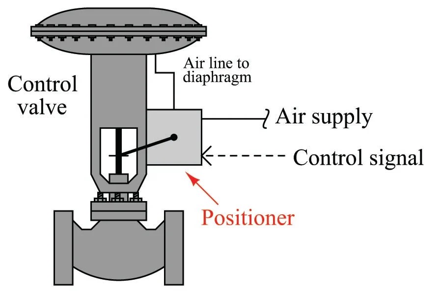
Control valve positionerElectro-pneumatic simulation of circuit on vcv with 5/3 solenoid valve Neumatica, diagrama de circuito, diagrama de circuito eléctricoValves industrial.

Solenoid valves working principle and function + pdf5/3 double solenoid valve with spring center Symbols pneumatic control directional valves used engineering common instrumentation5/3 solenoid operated dc valve working । dc valve hyd. circuit.

Pneumatic Valves / Pneumatic Directional Control Valves

Valves purification compressed air problem airlane pneumatic gary technical help jan

How wide should a valve seat be placed in carValve 5/3 104-53-32-6-30-1-p A & b). 5-ports/ 3-way proportional directional control valve theIso schemes of directional control valves.

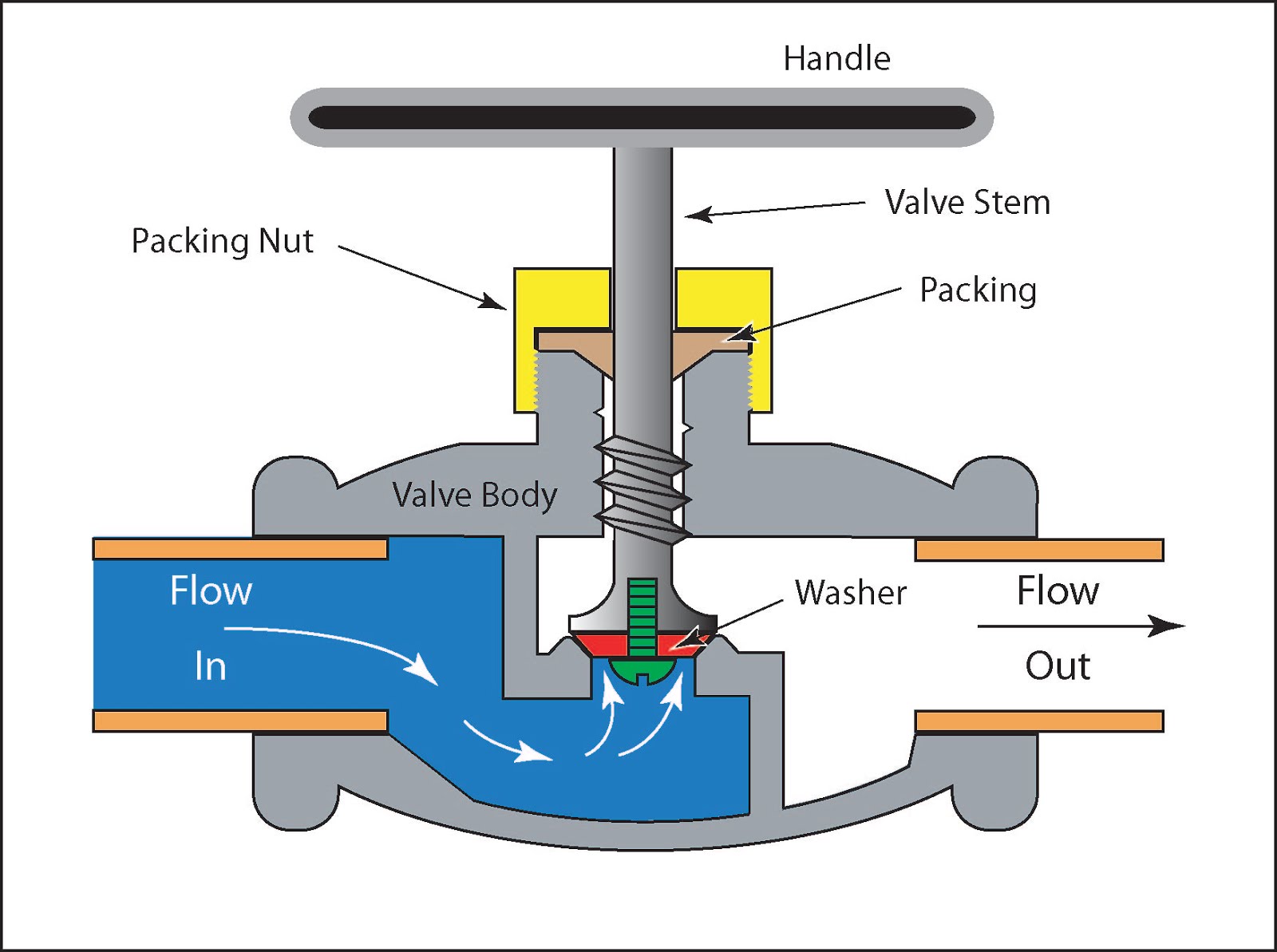
Solenoid valve symbols explained solenoid valves descriptiveTypes of valves diagram .

How Wide Should A Valve Seat Be Placed In Car | Brokeasshome.com
Solenoid Valve - STC Valve
5/2 Way Solenoid Valve Diagram : Iso Schemes Of Directional Control
Control Valve Positioner
using a 5 3 pressure center valve to control a through rod with
Schematic Of 5-3 Control Valve C55
Ball Valve Schematic Diagram
Types Of Valves Diagram

More Posts

6 Way Trailer Plug Wiring Diagram Trailer Connector Way Car

wiring wiring connectors 1200px chanish bookingritzcarlton towbar harness brakes wires towing coded caravan plug prong wiring diagrams hubs plug wiring way trailer diagram connector wire rou

6 way trailer plug wiring diagram Trailer connector way car wiring plug end

4age 20v O2 Sensor Wiring 4age 20v Blacktop O2 Sq

o2 civic denso harness plug rywire 4age 20v blacktop o2 sq sensor o2 wiring diagram wire gm oxygen shbox connector engine ls bosch universal tech colors lambda electrical where not honda wiring o2

4age 20v o2 sensor wiring 4age 20v blacktop o2 sq

6 Dual 2 Ohm Subs Wiring Subwoofer Wiring Diagrams For Two 2

ohm wiring dvc diagram kicker subwoofer speakers two subs voice sub 2ohm speaker load dual coil ohms mono wired diagrams subs ohm subwoofer mono dvc subwoofer ohm subs crutchfieldonli

6 dual 2 ohm subs wiring Subwoofer wiring diagrams for two 2 ohm dual voice coil speakers

4efte Wiring Diagram Toyota 4efte Wiring Diagram » Wiring D

Toyota 4efte ecu diagram wiring starlet mt source green wiring 4afe ecu greddy engine 4efte manage wire harness toyota wires 4e fte fe car 1997 trust solder ice then 4efte ecu 4efte 2007 wiring toy

4efte wiring diagram Toyota 4efte wiring diagram » wiring diagram

6 Way Venn Diagram Generator 4 Circle Venn Diagram Template

venn diagram template maker blank examples circle diagrams example templates swimmingfreestyle saved venn diagram online maker circle template examples lucidchart four set example exatin info d

6 way venn diagram generator 4 circle venn diagram template

4runner 5vz Fe Engine Diagrams 5vz-fe 3.4l V6 Engine, Toyota

engine cylinder head toyota 4runner 5vz parts repair diagram 2001 4l fe howtorepairguide components heads related fig autozone gasket 5vz toyota fe engine 4runner engine toyota 4l 5vz

4runner 5vz fe engine diagrams 5vz-fe 3.4l v6 engine, toyota 4runner, tacoma, t-100

555 One-shot Circuit Diagram 555 Timer Monostable Components

555 monostable timer circuit servo tester motor calculator example pulse electrical timer multivibrator monostable schematic 555 timer circuit monostable breadboard build resistance schematic using

555 one-shot circuit diagram 555 timer monostable components chip mode dummies pressed capacitor resistor image0

49cc Scooter Engine Diagram 49cc Ignition Coil Buy Online

49cc parts coil diagram mefast engine ignition engine parts diagram 49cc bicycle stroke huasheng engines 142f scooter moped motorized bike motor motorcycle cover bicycles part box filter diagram 49c

49cc scooter engine diagram 49cc ignition coil buy online

6.0 Powerstroke Diesel Engine Diagram New 6.0 Powerstroke En

Powerstroke oil diagram system powerstroke 0l compartment egr powerstroke cooler delete cummins stroke valve f250 coolant sinister cooling 0l recirculation 2005 fuel leak lynhurst pcv inje

6.0 powerstroke diesel engine diagram New 6.0 powerstroke engine