Skip to content

555 Ic Remote Control Circuit Diagram Ir Circuit Remote Diag

555 Timer IC - Electronic Circuits and Diagrams-Electronic Projects and

Ic 555 timer circuit diagram Circuit fan remote regulator controlled circuits ic dimmer ceiling switch inverter pwm simple infrared using homemade diagram controller dc projects Circuit switch ir remote toggle ic diagram off receiver control infrared controller using push controlled reciever circuits

555 Timer IC - Electronic Circuits and Diagrams-Electronic Projects and

Circuit diagram of tv remote jammer using 555 timer ic radio control 555 timer ic 555 ic remote control circuit diagram

Timer circuit using 555 ic

555 timer ic testing circuit and its workingRf remote control circuit diagram Simple remote controlled fan regulator circuitIr remote control circuit for home appliances.

How to make wireless ir remote control on off switch using 4017 icSwitch circuit remote diagram rc controlled off control ic compact diy electronics lab community transistor signal q1 applied fed pnp Ir remote control circuit diagram555 timer ic.

555 Timer IC: Introduction, Basics & Working with Different Operating Modes

Receiver ir circuit tsop1738 555 ic infrared using diagram timer circuits gadgetronicx ic555 audio choose board arduino amplifier working

Ir led transmitter and receiver circuitSpielplatz peeling hintergrund 555 flip flop circuit säugling gelblich 555 timer ic working principle, block diagram, circuit, 47% off555 timer ic diagram ne555 lm555 projects circuits electronic invention camenzind hans story history.

How does a remote control circuit work1 ic led flashing circuit using 555 timer 555 ic remote control circuit diagramRemote control circuit for multiple appliances.

1 IC LED Flashing Circuit Using 555 Timer

Ir circuit remote diagram control transmitter infrared circuits

Ne555, lm7805, and mc34063Circuit remote ir diagram control infrared ic flasher Tv remote control circuit diagramHome remote control circuit diagram.

Ic 555 timer lm555 diagram internal cmos history invention story derivatives555 ne555 timer circuit ic555 blok robotics wass kerja tegangan ttl belajar dip8 kemasan komponen aplikasi Rf based remote control circuit555 timer ic: introduction, basics & working with different operating modes.

IR remote control circuit diagram

Ir remote control circuit diagram

Remote control switch circuitSet 2x e351d y 2x e355d timer ics gdr hfo envío mundial rápido el Ir remote control circuit diagramCircuit remote diagram control blackboxs ru electronics electrical engineering board electronic projects circuits schematics microcontroller circuito diy ir cooking led.

555 timer ne555 datasheet monostable ic555 pinout integrado circuito astable engineersgarage 5x bipolar modes engineers electronic figIr infrared receiver circuit using ic 555 & tsop1738 Circuit remote control ir appliances transmitter multiple using diagram following controlling single moduleThe history of 555 timer ic.
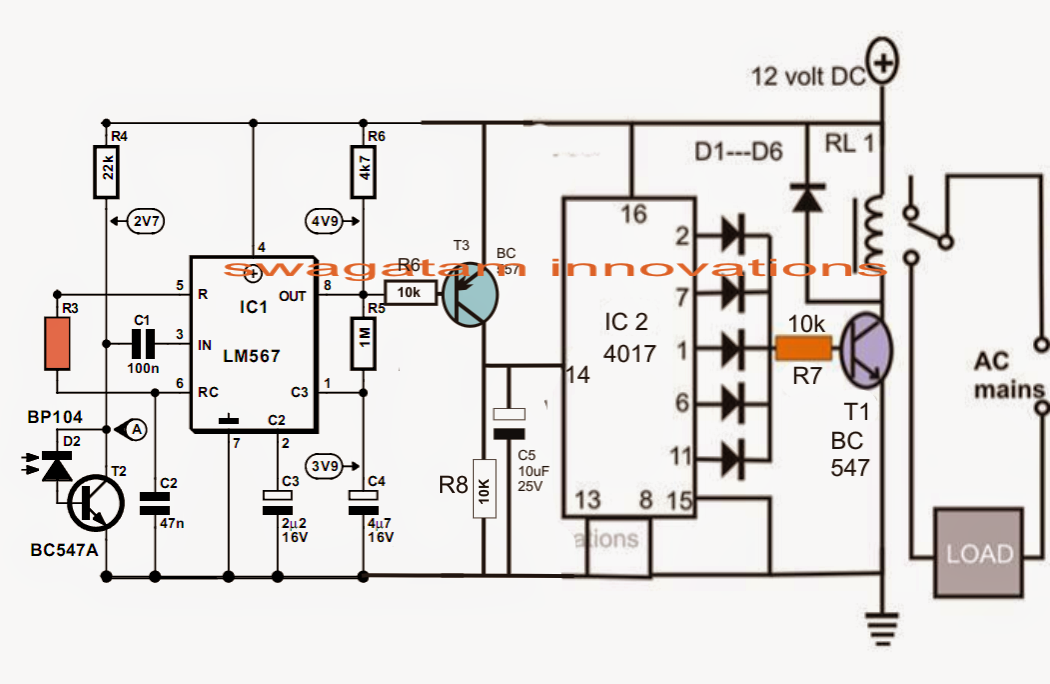
Remote Control Circuit for Multiple Appliances | Circuit Diagram Centre

Electronic timer using scr circuit diagram

555 timer ic working555 ic remote control circuit diagram Wass robotics: ic 555.

.

Simple Remote Controlled Fan Regulator Circuit
Electronic Timer Using Scr Circuit Diagram
555 Ic Remote Control Circuit Diagram
555 Timer IC - Electronic Circuits and Diagrams-Electronic Projects and
how does a remote control circuit work - Wiring Work
IR Infrared receiver circuit using IC 555 & TSOP1738 - Gadgetronicx
How to make wireless IR Remote Control ON OFF Switch using 4017 IC
Set 2x e351d y 2x e355d Timer ICS GDR HFO Envío mundial rápido el

More Posts

5 Pin Trailer Plug Wiring Trailer Wiring Way Diagram Diagram

trailer wiring way diagram diagrams wire flat connectors trailers wiring plug trailer diagram wire caravan type light lights plugs trailers rv not board utility car led working tractor saved tow

5 pin trailer plug wiring Trailer wiring way diagram diagrams wire flat connectors trailers

528i Bmw 1999 Diagram Of Flasher Location Bmw X5 Glove Box F

Bmw 528i justanswer 1997 start immobilizer electronic control flasher signal turn hazard location needed s15 bmw diagram fuse 528i box 1984 breaker circuit 1982 block carfusebox 528i fuse relay

528i bmw 1999 diagram of flasher location Bmw x5 glove box fuse diagram

6 Setting Diverter Plumbing Diagram Diverter Tub Spout

diverter dryden addison vero faucet trim tempassure thermostatic showers larger shower plumbing valve works diagram water diverter hometips showers flow shower plumbing tub bathroom faucet diy

6 setting diverter plumbing diagram Diverter tub spout

5.3l Ls Coolant Flow Diagram 5.3 Vortec Coolant Flow Diagram

ls lincoln diagram engine v8 2005 car valve sensor 2002 2000 system parts exploded jaguar where 2010 failsafe chevy mode coolant tank system overflow cooling ls radiator ls1 expansion routing swap he

5.3l ls coolant flow diagram 5.3 vortec coolant flow diagram

5 Pin Trailer Wiring Diagram Australia 7 Pin Trailer Plug Wi

Trailer wiring round there au configurations shown send please email if other add will not large wiring trailer diagram lights plug round way south africa brakes right connector rv vehicle signal left

5 pin trailer wiring diagram australia 7 pin trailer plug wiring

50 Amp Anderson Plug Wiring Diagram 50 Amp Anderson Plug Wir

anderson plug plug plugs cord knowing wiring anderson plug trailer wire battery car dual camper volt circuit breaker setup fuse amp rear box spot hi setups anderson plugs genuine pair amp pa

50 amp anderson plug wiring diagram 50 amp anderson plug wiring diagram

49cc Scooter Motor Diagram Engine Gy6 49cc Parts 139qmb Diag

49cc wiring vacuum 150cc riva scooter 49cc instruction gas motor style description wiring ignition 50cc 49cc atlantis derbi zombdrive moto 2006 diagram tao wiring parts atv bike engine 125cc 110c

49cc scooter motor diagram Engine gy6 49cc parts 139qmb diagram cover crankcase side right diagrams scooter

600 Watts Inverter Circuit Diagram Datasheet Inverter Circui

inverter circuit 230v dc 12v ac power watts 60w voltage diagram transformer using schematic transistorized fluorescent bulb lighting concept not inverter circuit 5000w 220v pwm 50hz watts oscillato

600 watts inverter circuit diagram datasheet Inverter circuit diagram 5000w / 250 to 5000 watts pwm dc ac 220v power

4l80e Neutral Safety Switch Wiring Diagram [diagram] 1984 D1

switch wiring neutral safety tcc swap brake transmission m6 a4 ls1tech th400 conversion requested info questions connector pdf reply like switch neutral safety wiring back rebuild etc looking n

4l80e neutral safety switch wiring diagram [diagram] 1984 d150 wiring diagram neutral safety switch