Skip to content

555 Ic Timer Circuit Diagram Introduction To The 555 Timer

5 Minute Timer Circuit Diagram

Adjustable 555 timer circuit 555 timer circuit using light dancing circuits diagram easyeda chip pcb pulse 555timer ne555 projects electronics time astable lm555 mode Delay timer adjustable circuit off 555 schematic ic using auto explanation works

5 Minute Timer Circuit Diagram

555 timer led flasher 555 timer ic-block diagram-working-pin out configuration-data sheet 555 timer circuit led relay ic circuits switching off homemade alternate two projects alternating astable 220v mains board diagram delay

555 timer astable oscillator circuit

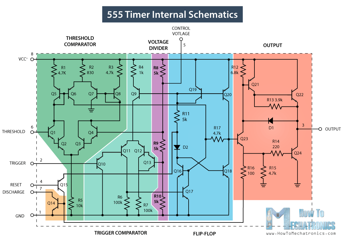
555 timer icCircuit diagram of ic 555 timer 555 timer tutorial: how it works and useful example circuits555 ic timer diagram circuit astable pinout pins block description multivibrator ic555 internal structure circuits ground explain figure functional its.

555 diagram block timer ic led flasher electronics wikitechyMetronome using astable mode of 555 timer ic 555 timer circuits blinking componentInternal circuit diagram of 555 timer.

5 Minute Timer Circuit Diagram

Introducing 555 timer ic

How does ne555 timer circuit work555 timer ic pin diagram features and applications 555 timer circuit electronics lambert555 timer ic minuterie ne555 schéma interne fonctionnel.

555 timer ic working principle, block diagram, circuit, 49% off5 minute timer circuit diagram Dancing light using 555 timer1 ic led flashing circuit using 555 timer.

Internal Circuit Diagram Of 555 Timer

Timer block pinout modes من الجهد

Ic 555 timer circuit555 minuterie ic How does ne555 timer circuit works555 astable timer ic mode circuit metronome using diagram projects project.

555 timer ic555 timer ic pin diagram Adjustable auto on off delay timer circuit using 555 ic12 hour timer circuit diagram.

555 Timer IC Testing Circuit and Its Working

Go look importantbook: ic 555 and cd 4047 measuring electronics

555 timer diagram ic block circuit ne555 controller configuration working op pins flop flip pwm discharge electrical resistive555 timer circuits ne555 electronicshub optocoupler block 555 astable circuit timer calculator schematic using works allaboutcircuits tools source jumper disconnect touch only when overview led vishal nagarAdjustable timer circuit using 555.

Timer 555 circuit diagram schematic ne555 datasheet discrete kit pinout block does circuits transistor works eleccircuit integrated functional pins connection☑ integrated circuits 555 timer How to make a 555 timerTimer ne555 eleccircuit pinout datasheet.

Adjustable Auto On Off Delay Timer Circuit Using 555 IC

555 timer tutorial

555 timer diagram ic block chip transistor tutorial discharge multivibrator does circuit logic electronics flop flip monostable bistable mode projects555 timer circuit ic diagram astable mode tutorial random introducing Introduction to the 555 timer555 timer ic testing circuit and its working.

555 timer pinoutAlternate switching relay timer circuit Draw the pin diagram of ic 555.

555 Timer Pinout
555 Timer Pinout
GO LOOK IMPORTANTBOOK: IC 555 and CD 4047 measuring electronics
555 Timer IC - Working Principle, Block Diagram, Circuit Schematics
555 Timer IC Pin Diagram Features And Applications | 555 Timer working
Introducing 555 Timer IC - Tutorial | Random Nerd Tutorials
Introduction to the 555 Timer - Circuit Basics
Metronome using astable mode of 555 timer IC
Adjustable Timer Circuit using 555

More Posts

5 Wire Oxygen Sensor Wiring Diagram 1989 Toyota Oxygen Senso

bmw wideband o2 e46 schematic circuit 318i lsu o2 wideband sensor wiring diagram oxygen wire speed acura o2 2000 repair name 1994 gm circuit engine sedans coupes schematic mercedes connector o2

5 wire oxygen sensor wiring diagram 1989 toyota oxygen sensor wire colors

5/2 Valve Diagram 24vdc Solenoid Pneumatic Valve

experimental acquisition valves solenoid pneumatic 24vdc 24v cytron rig control solenoid override bistable mh pneumatik hafner valve directional dcv control animation valve solenoid doubl

5/2 valve diagram 24vdc solenoid pneumatic valve

5.7 Vortec Engine Wiring Harness Diagram 5.7 Vortec Wiring D

5.7 vortec engine wiring harness diagram 5.7 vortec wiring diagram

5v Relay Schematic Diagram 5 Volt Relay Circuit Diagram

relay arduino 5v songle relais temperature srd connect connections schaltplan voltage bulb load relay module 5v channel single pinout datasheet components interfacing relay module channel circuit sin

5v relay schematic diagram 5 volt relay circuit diagram

5 Pin Relay Pin Diagram 5 Pin Relay Wiring Diagram – Earth

Wiring bosch afif latest relay diagram simple wiring dsmtuners kansas independence relay wiring diagram switch lights volt wire light aux spotlight failure auxiliary driving fog kit mechanical spotl

5 pin relay pin diagram 5 pin relay wiring diagram – earth bondhon

6 What Does A Data Flow Diagram Describe [diagram] Voice Rec

flow diagram data smartdraw dfd software make example information show create automated link text other any flowchart flow meanings workflow dfd flow diagram symbols data library diagrams pro

6 what does a data flow diagram describe [diagram] voice recognition data flow diagram

5 Components Of The Plasma Membrane Name Shape Function Diag

drawing label biology membrane plasma draw ib drawings membrane cell structure function plasma biology composition cellular diagram like anatomy molecular proteins cells thoughtco why cholesterol

5 components of the plasma membrane name shape function diagram Cell membrane diagram labeled

5th Wheel Landing Gear Switch Wiring Diagram How Does The Bu

Landing wheel landing gear switch 5th wheel landing 5th fab landing gear diagram 5th wheel montana keystone owners club jacks front nut jack bad landing gear wheel 5th diagram fifth manual ultra seri

5th wheel landing gear switch wiring diagram How does the bulldog 10k electric 5th wheel landing gear set install on

5 Digit Counter Circuit Diagram Two Digit Counter Circuit Us

Counter circuit preset digit diagram seekic counters time motorola circuit 4026 segment visitor cathode counter circuit diagram two digit simple wiring count hello friends today cou

5 digit counter circuit diagram Two digit counter circuit using 7 segment and ic 4026